Fixing Radio Glitch issues
by Andy Watkins.
September 2008
Updated October 2008
Ever since I acquired my Roundhouse tender loco, I've had issues with the radio control, making it disappointing to drive. I own another loco from the same manufacturer, one without a tender, and that one has been OK, so I assumed the problems lay in the fact that the loco had a tender, and the differences in the way the radio control gear was laid out.
 The symptoms were that the servos would occasionally decide to do
their own thing, irrespective of what the transmitter
was telling them to do. Sometimes, the servo on the regulator
would shake up and down, causing the loco to stop, sometimes
the servo on the reversing gear would jitter, causing the whole
loco to stop suddenly and go again. In the worst cases, the loco
would go backward for a moment, or the regulator would open
suddenly without warning.
The symptoms were that the servos would occasionally decide to do
their own thing, irrespective of what the transmitter
was telling them to do. Sometimes, the servo on the regulator
would shake up and down, causing the loco to stop, sometimes
the servo on the reversing gear would jitter, causing the whole
loco to stop suddenly and go again. In the worst cases, the loco
would go backward for a moment, or the regulator would open
suddenly without warning.
I noticed that the radio jitter happened at the same place on the track, every time the loco went round. This suggested that it wasn't a problem with the electronics themselves, but something to do with that particular spot on the line. Because of this, I did wonder for a while if the loco had a mechanical problem in the valve gear.
At first, I thought the servo jitter might be caused by electrial interference from some nearby metalwork, but with the help of a friend, who knows about all things to do with Radio Frequency and Electronics, I tried a number of things to isolate the issue, and eventually suceeded in getting the loco to run smoothly.
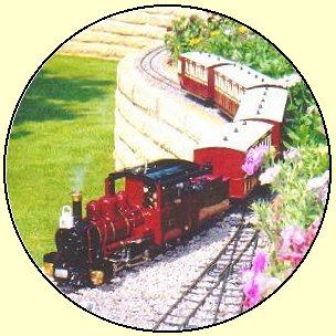
The loco is a Bangalore Belle, based on the Roundhouse Fowler loco. (see Suppliers). I understand that radio glitching issues are a common problem on their tender locos, so this may be relevant for any such loco. Recently, I came across a gentleman who ripped the radio and servos out of his Fowler, precisely because of the issues he was having, and he now drives his manually.
For me, however, radio control is a must, and I wanted to see if I could fix the issue before resorting to a servo smoother.
It turns out that the radio interference is caused by two large areas of metal coming into momentary electrical contact with each other. A large area of metal might be the cab and boiler assembly, or the tender; anything which is soldered, welded or tightly screwed together. Where something can move, such as on the pin coupling between the loco and the tender, the electrical connection isn't guaranteed. This causes the electrical connection to come and go, which causes the interference, resulting in the servos going epileptic.
A Common Earth
The first step was to join the locomotive and the tender electrically. The pin still provides the mechanical connection, but, as explained above, doesn't guarantee electrical connection. So I ran a bit of wire between the two, and screwed the wire to part of the bodywork at each end. The loco body and the tender body are now always at the same voltage.
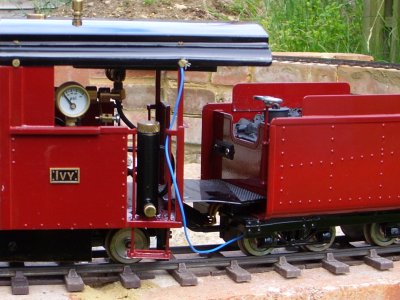
In the Photo above, the blue earthing wire can be seen coming out of the base of the tender, and up into the cab, where it is wrapped round a brass bolt on the bodywork.
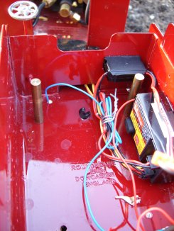
(The blue wire can be seen inside the tender in another photo below. It is fixed to one of the brass pillars inside the tender, which hold up the fake coal load.)
Unfortunately, this earthing didn't help on its own. It has probably helped to solve the problem, as it now guarantees that there won't be a voltage difference between the loco and the tender, but there was still more to do to get to the bottom of the problem.
Insulating the bogies
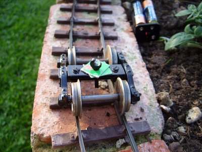
My friend suggested next that where the bogies are attached to the tender with a brass bolt, we could be getting intermittent electrical contact interfering with the radio reception. He suggested I get some nylon bolts to replace the brass ones.I had trouble finding some nylon bolts of the correct size, but I had a flash of inspiration that I could use a plastic pin and plastic or card "washers" to achieve the same effect, just to see if this would solve the problem. Now, where to find a suitable plastic pin which wouldn't just fall through the hole? ...
The answer came from my son's room...
I discovered that a Lego Spanner has a narrow enough shaft to fit through the hole where the brass bolt goes. It has a wide head, so it won't fall through onto the track, and also it's short enough that it won't hit the sleepers.
In the photo above, the spanner is visible, sticking out of the hole where the brass bolt is supposed to go (the is duplicated for the other bogie under the tender).
Below, you can see what it would look like if the tender were transparent. The plastic Lego spanner keeps the bogies in position beneath the tender, and the cereal-packet washers provide electrical insulation between the bogie and the tender.
The whole arrangement is a little wobbly, and fiddly to assemble, but it was enough to demonstrate if insulating the bogies would do the trick.
So, did it work?
I steamed up the loco and carefully drove it round my circle of track. It got about 3/4 of the way round, and then the radios went silly again. However, this time, the servos did not respond at all to moving the joysticks on the radio suggesting something else was happening. I suspected flat batteries (flat enough to prevent radio reception, but enough juice to move the servos).Replacing the batteries with fresh ones resulted in the smoothest run I've ever had with this loco, and no servo glitching. It was a huge relief to see my loco running smoothly round the track. The only issue is that if you go round corners too fast, the tender rocks (it look like it's going up on 2 wheels) because the Lego spanner doesn't keep the tender and bogies close together. That's a mechanical problem which will be solved when I've found some suitable plastic bolts.
This run also demonstrated that there's nothing wrong with the valve gear, as I had previously thought, which is also a huge relief.
I'm ordering some nylon M3 4BA[1] bolts to see if they'll work. I'd also be pleased to hear if this article has been useful to you.
Addendum
After I published this article, I received a great deal of positive feedback on the 16mmngm e-group. I thought it was worth mentioning some of the comments here.Roundhouse were interested in my article, and corrected me that the bolts are 4BA. (that'll be why they looked like M3.5 then!!). I also had a number of suggestions as to where to obtain nylon bolts.
It was reported that a servo-smoother didn't help, that a Battery Elimination Circuit for an electronic speed controller can make matters worse, and that running in reverse can make things better (that's OK if you like running tender-forwards all the time)
A number of people suggested that insulating the coupling pin and the fall plate helped them solve the problem. Insulating the locomotive from the tender works as well as joining them electrically, I guess. Either way, you don't get sudden voltage changes in the bodywork sections. It was also suggested that the glitching problems get worse as the paint wears off around the coupling pin and hole.
I am grateful for the many responses I received. This is clearly an issue that a number of loco owners have already experienced.
Subsequent runs have shown that radio interference is now only caused by external factors, such as metal fences in the way, and normal stuff which gets in the way of 40 MHz control. I added a strip of black electrical tape to the bottom of the fall plate, and inspected the coupling pin. The pin is already made of an insulating material, so no work was needed there. If radio interference does occur, it can be prevented from happening at the same point on the line by moving the radio. The only way around this would be to upgrade the transmitter and receiver to 2.4 GHz, which uses digital signals with error-correcting.